
 Jinan Huanya Auto Parts Co., Ltd.
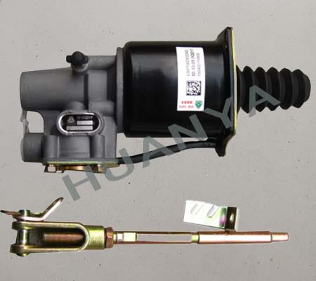
Clutch Booster Cylinder Assembly
1. Basic Part Information
Part Name: Clutch Booster Cylinder Assembly (commonly known as "clutch booster" or "pneumatic clutch slave cylinder")
Part Number: LG9704230224 (a common part number for this type of component)
Appearance Features:
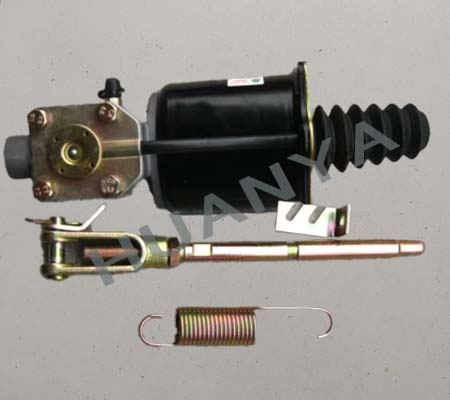
Main Body Structure: A gray metal cast hydraulic/pneumatic control valve body on the left, connected to a black cylindrical pneumatic air chamber on the right.
Pushrod Section: The far right end features a black, corrugated dust boot protecting the internal piston pushrod.
Accessory Component: A pushrod connecting assembly for the release fork (with a yellow grease fitting adjusting rod), used to transmit the booster cylinder's thrust to the transmission release fork.
2. Applicable Models & Installation Position
Applicable Models: Mainly suitable for Sinotruk HOWO light truck series, such as Hanjiang, Tongshuai, and other models.
Installation Position: Mounted on the front side of the transmission housing and connected to the clutch master cylinder (located under the cab floor) via a high-pressure hydraulic line.
3. Main Functions & Role
Reducing Driver Fatigue: Heavy-duty truck and diesel vehicle clutches have large friction discs and high clamping force. Relying solely on leg strength to depress the pedal would be very strenuous. The clutch booster cylinder uses pneumatic assistance to significantly reduce the pedal effort required, improving driving comfort.
Ensuring Full Disengagement: By combining hydraulic and pneumatic force, the booster provides sufficient thrust to press the clutch release bearing accurately against the release levers, ensuring complete clutch disengagement — preventing hard shifting or gear clash.
Working Principle (Brief): When the driver depresses the clutch pedal, the clutch master cylinder generates hydraulic pressure, which is sent to the booster cylinder. The hydraulic fluid both pushes the main piston and opens an air valve, allowing compressed air into the air chamber. Under the combined force of hydraulics and pneumatics, the pushrod extends outward, moving the release fork — which then disengages the clutch.